The patented TS1250 is a next-generation controller designed from the ground up for superior performance, easy installation and outstanding reliability. Using state-of-the-art microcontroller technology, the TS1250 provides both standard and enhanced user selectable flash patterns:
Standard MUTCD Pattern (50 or 60 flashes per minute)
Seven MUTCD Compliant Enhanced Patterns
Auto-sequencing Flash Pattern Mode
Each enhanced flash is composed of a unique pattern of pulses sent during the flash period and conforms to MUTCD requirements. The Auto-sequencing Flash Pattern Mode continuously cycles through all seven enhanced flash patterns, displaying a single pattern during each activation period.
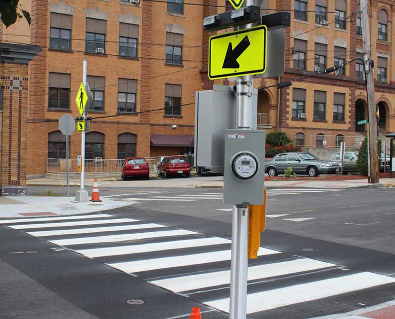
The TS1250 supports a wide range of crosswalk system configurations, and is compatible with standard activation devices (push-buttons) and standard pre-warning devices (LED flashing signs and beacons).
Why Our Crosswalk System Controller Is Better
Superior Performance
Activation devices supported simultaneously: Devices can be connected simultaneously to the same controller to activate the light fixtures.
Manual Dimming Control Supported: Dimming fixtures can now be dimmed with the use of a knob in the controller.
Photocell Dimming Control Supported: Dimming fixtures can be dimmed at night to reduce glare and then return to full brightness during the day.
TSC Enhanced Flash Patterns and Auto-sequencing Flash Pattern Mode are designed to maximize pedestrian safety by increasing driver awareness and response to warning systems.
Generation of contrasting flash patterns to crosswalk and pre-warning systems is supported by dual DC outputs.
An activation override switch provides for continuous flashing of crosswalk during sporting and other high-traffic events.
Easy Installation
Conveniently located, clearly labeled wiring blocks simplify field wiring and allow easy access during installation.
LED status and digital displays allow easy verification of system operation and configuration during setup and testing.
Controls are provided for easy onsite customization of system operation.
Outstanding Reliability
Conformal coating material on circuits protects against moisture, dust, chemicals and temperature extremes.
Internal components are protected by input and output surge protection, and replaceable fuses to protect against output overload conditions.
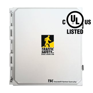
Polycarbonate enclosure with 316 stainless steel dual locking latch mechanism provides protection from adverse weather and security from unauthorized access. NEMA 3R/4X compliant. Polycarbonate is non-corrosive and non-conductive. It is easier to modify, weighs less, and has a longer life cycle than steel enclosures.
The system controller shall be model SC-TS1250-AC as marketed by Traffic Safety Corporation or approved equal. In order to be approved equal, the proposed device must satisfy the following requirements:
System controller shall support multiple MUTCD compliant regular and enhanced flash patterns, and be capable of auto-sequencing through all enhanced flash patterns, one pattern per activation period.
System shall support operation of multiple activation devices simultaneously.
System shall support both manual and photocell dimming control.
Output pattern operation, power limitations and output flash pattern selection:
Output A (Primary DC Power Output)
The maximum DC power output of the primary (10 amp limit) shall be 120 watts. The output flash pattern shall be selected by the pattern selector control located on the control card.
Output B (Secondary DC Power Output)
The maximum DC power output of the secondary (10 amp limit) shall be 120 watts. The output flash pattern shall be selected by a set of output mode selector switches ( 1-4 ) located on the control card: 1-Same as primary; 2-In sync with primary, but non-enhanced; 3-Non-enhanced complement of primary; 4-Continuously on while primary is flashing. Notes: (a) Enhanced flash patterns cannot be used when operating in wig-wag mode. (b) Only one output mode switch can be on (closed) at a time for proper operation of the system.
Combined Power Output: The combined output power of the primary and secondary DC outputs shall be 120 watts.
System controller shall be based on an integrated, high-speed 8-bit microcontroller with non-volatile firmware and memory. All settings must be retained in the event that input power is removed.
System controller shall include the following controls and indicators:
Power LED Indicator: A visual indicator LED shall be provided to indicate the “power on” condition.
Activation Duration Setting: Activation duration shall be field adjustable in one-second increments, over a range of 1 to 99 seconds. Duration setting shall be displayed on a digital numeric display.
Flash Pattern Setting: Flash pattern setting shall be field adjustable and be displayed on a digital numeric display.
Push-Button Test and LED Indicator: System shall include an internal push-button used to activate the system during field tests. System shall include a visual indicator LED to indicate internal push-button and external activation device calls.
Override Switch: System shall include an override switch to allow switching from manual system activation to continuous system activation.
Output LED Indicators: System shall include visual indicator LEDs which indicate: system activation, primary output (A), and secondary output (B) status.
System shall support activation from standard contact-closure type push-buttons and push-buttons with audio message capability.
System shall provide a field selectable option to allow an activation call to be ignored, or be used to reset the cycle during an ongoing crossing cycle.
System Protection: All DC outputs shall be protected with a replaceable fuse. In the AC powered model, the input AC voltage shall be protected by a thermal-magnetic circuit breaker integral to the AC power supply. The AC power supply shall include transient surge protection. All DC electronics shall be electrically isolated from the AC input voltage.
System Controller Enclosure: The system shall include a single enclosure for ease of installation. The system shall be housed in a NEMA 3R/4X compliant, polycarbonate enclosure with approximate dimensions of (14″ H x 12″ W x 6″ D) to provide protection from adverse weather conditions. The enclosure shall be supplied with a 316 stainless steel dual locking latch mechanism for security from unauthorized access.
Warranty: The crosswalk system controller shall be warranted against defects in workmanship and materials for one year from date of shipment and is eligible for TSC’s 5-Year Limited System Warranty.
– A: NEMA 3R/4X Compliant Enclosure – B: TS1250 Back Panel (customer supplied enclosure) – C: PA Back Panel (customer supplied Power Adapter enclosure) – DP: Dimming with Photocell
* BDL3 Push-Button Stations must be ordered with wireless interface option (-W).
Notes:
1. Please contact TSC to discuss any modifications or additions to the controller system.
2. Pole Mounting Bracket Kit (SC-626005) supports U-bolts for pipe sizes 2″ to 4″ and 6″ to 8″. U-bolts and pipe not included.
3. With dimming option, photocell can be bypassed if dimming needs to be done manually.
4. Shipping dimensions: 15″ x 15″ x 10″ (38cm x 38cm x 25cm). Shipping weight: 11 lb. (5 kg)
Improve emergency crew response time by giving advanced warning to drivers that emerg Read More
Get the longest warranty in the industry
We offer a 5-Year Warranty – the longest in the industry – on inpavement crosswalk warning systems. For over 20 years, we’ve been building high quality, certified traffic products.