The patented TS1250 is a next-generation controller designed from the ground up for superior performance, easy installation and outstanding reliability. Using state-of-the-art micro-controller technology, the TS1250 provides both standard and enhanced user selectable flash patterns:
Standard MUTCD Pattern (50 or 60 flashes per minute)
Seven MUTCD Compliant Enhanced Patterns
Auto-sequencing Flash Pattern Mode
Each enhanced flash is composed of a unique pattern of pulses sent during the flash period and conforms to MUTCD requirements. The Auto-sequencing Flash Pattern Mode continuously cycles through all seven enhanced flash patterns, displaying a single pattern during each activation period.
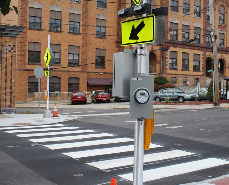
The TS1250 supports a wide range of crosswalk system configurations, and is compatible with standard activation devices (push-buttons, bollards) and standard pre-warning devices (LED flashing signs and beacons).
Why Our Crosswalk System Controller Is Better
Superior Performance
Activation devices supported simultaneously: Push-buttons, Motion Sensors, and Bollards can be connected simultaneously to the same controller to activate the light fixtures.
Manual Dimming Control Supported: Dimming fixtures can now be dimmed with the use of a knob in the controller.
Photocell Dimming Control Supported: Dimming fixtures can be dimmed at night to reduce glare and then return to full brightness during the day.
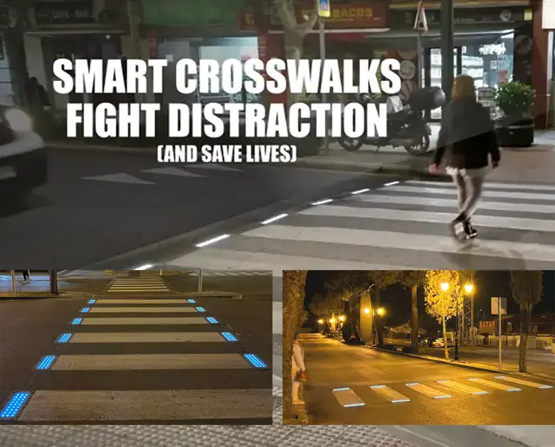
TSC Enhanced Flash Patterns and Auto-sequencing Flash Pattern Mode are designed to maximize pedestrian safety by increasing driver awareness and response to warning systems.
Generation of contrasting flash patterns to crosswalk and pre-warning systems is supported by dual DC outputs.
An activation override switch provides for continuous flashing of crosswalk during sporting and other high-traffic events.
Easy Installation
Conveniently located, clearly labeled wiring blocks simplify field wiring and allow easy access during installation.
LED status and digital displays allow easy verification of system operation and configuration during setup and testing.
Controls are provided for easy onsite customization of system operation.
Outstanding Reliability
Conformal coating material on circuits protects against moisture, dust, chemicals and temperature extremes.
Internal components are protected by input and output surge protection, and replaceable fuses to protect against output overload conditions.
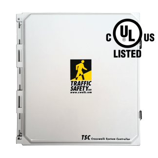
The white powder coated aluminum enclosure provides protection from adverse weather and security from unauthorized access. NEMA 3R compliant. Dimensions: 20.8″ H x 16.0″ W x 14.4″ D.
The system controller shall be model SC-TS1250-SP as marketed by Traffic Safety Corporation or approved equal. In order to be approved equal, the proposed device must satisfy the following requirements:
System controller shall support multiple MUTCD compliant regular and enhanced flash patterns, and be capable of auto-sequencing through all enhanced flash patterns, one pattern per activation period.
System shall support operation of multiple activation devices simultaneously.
System shall support both manual and photocell dimming control.
Output pattern operation, power limitations and output flash pattern selection:
Output A (Primary DC Power Output)
The actual maximum power output shall be specified in the sizing report.
Output B (Secondary DC Power Output)
The actual maximum power output shall be specified in the sizing report. The output flash pattern shall be selected by a set of output mode selector switches (1-4) located on the control card: 1-Same as primary; 2-In sync with primary, but non-enhanced; 3-Non-enhanced complement of primary; 4-Continuously on while primary is flashing. Notes: (a) Enhanced flash patterns cannot be used when operating in wig-wag mode. (b) Only one output mode switch can be on (closed) at a time for proper operation of the system.
The combined output power of the primary and secondary DC outputs shall be specified in the sizing report.
System controller shall be based on an integrated, high-speed 8-bit microcontroller with non-volatile firmware and memory. All settings must be retained in the event that input power is removed.
System controller shall include the following controls and indicators:
Power LED Indicator: A visual indicator LED shall be provided to indicate the “power on” condition.
Activation Duration Setting: Activation duration shall be field adjustable in one-second increments, over a range of 1 to 99 seconds. Duration setting shall be displayed on a digital numeric display.
Flash Pattern Setting: Flash pattern setting shall be field adjustable and be displayed on a digital numeric display.
Push-Button Test and LED Indicator: System shall include an internal push-button used to activate the system during field tests. System shall include a visual indicator LED to indicate internal push-button and external activation device calls.
Override Switch: System shall include an override switch to allow switching from manual system activation to continuous system activation.
Output LED Indicators: System shall include visual indicator LEDs which indicate: system activation, primary output (A), and secondary output (B) status.
System shall support activation from standard contact-closure type push-buttons and push-buttons with audio message capability.
System shall provide a field selectable option to allow an activation call to be ignored, or be used to reset the cycle during an ongoing crossing cycle.
System Protection: Outputs A and B shall be protected by a replaceable fuse.
System Controller Enclosure: The system shall include a single enclosure for ease of installation. The system shall be housed in a NEMA 3R compliant, white powder coated aluminum enclosure with approximate dimensions of (20.8″ H x 16.0″ W x 14.4″ D) to provide protection from adverse weather conditions. The enclosure shall be supplied with a keyed latch mechanism for security from unauthorized access.
Solar Modules and Mounting Structures:
The modules shall consist of a minimum of 36 crystalline cells in series. Cells shall feature an anti-reflective coating and a low iron glass covering. Cells shall be encapsulated to protect them from the environment. Each module shall feature a weather tight junction box for connecting the array output cable to the module terminals. Power modules greater than 60 watts shall feature a minimum warranty of 15 years for power output. Modules, 20 to 50 watts, shall feature a minimum warranty of 5 years for power output. All modules shall feature an anodized aluminum frame for mechanical support.
Solar modules shall be able to be securely mounted to the top of a 4.5″ O.D. pole assembly, or attached to larger diameter poles with a side pole mount structure that has been specifically designed to hold solar modules. All of the necessary hardware to install the modules to the mounts, and the mounts to the pole, shall be included in the bid. Security hardware for securing the module to the mount shall be included along with any special tools required for the hardware. Mounts made of steel will be powder coated or hot dip galvanized. Aluminum module mounts can be either powder coated or feature a mill finish.
System Batteries:
The system shall come equipped with the number and type of batteries detailed in the sizing report. The battery type shall be a sealed, maintenance-free, valve-regulated design. The battery shall be a Gel or Absorbed Glass Mat (AGM) type, to suspend the electrolyte making it immobile.
Gel batteries using a thixotropic gel to suspend the electrolyte, shall also be considered an acceptable alternate.
Acceptable battery sizes that can be accommodated shall include either one or two batteries, up to group size 31.
General Specifications: Solar power supplies provided for use with in-pavement crosswalk systems shall be designed to act as a stand-alone power source for the system. Any response to bid shall require a specification report containing the following data:
Site information shall take into account average monthly solar insolation at a 45° tilt angle, average monthly temperature at the site, and latitude and longitude of the nearest city/town.
In the event that no data point exists for the given city/town where the installation will be done, sizing shall be prepared for the nearest data point available around the installation site featuring similar geographical and/or climatic conditions.
Load tabulation shall be included to detail the number, type and duty cycle of all loads in the system.
The report shall include the type of solar module to be used by model and manufacturer.
Type of battery shall be provided by model and brand name. Projected days of autonomy shall be provided with the battery information. The system shall support a minimum autonomy of 5 days, unless otherwise specified by the customer.
The worst case array to load ratio shall also be provided. Minimum acceptable array to load ratio for the solar system shall be 1.05 or greater in December when using the maximum power draw for the loads.
A system derating factor shall be included in the sizing report component sizing calculations to cover any losses from solar panel output mismatch, dirt/dust accumulation on panels, aging and losses due to system wiring. Losses may appear as a combined derating factor, but a thorough description of the sources of all losses accounted for shall be provided. Failure to provide a sizing report shall be considered non-responsive and result in disqualification, in which case the bid will be rejected.
Warranty: The crosswalk system controller shall be warranted against defects in workmanship and materials for one year from date of shipment and is eligible for TSC’s 5-Year Limited System Warranty. Excluded from the TSC warranty are the solar array and battery. These components are covered under the warranty of their respective manufacturer.
* BDL3 Push-Button Stations must be ordered with wireless interface option (-W).
Notes:
1. Please contact TSC to discuss any modifications or additions to the controller system.
2. Pole Mounting Bracket Kit (SC-626005) supports U-bolts for pipe sizes 2″ to 4″ and 6″ to 8″. U-bolts and pipe not included.
3. With dimming option, photocell can be bypassed if dimming needs to be done manually.
Solar Panel
Qty.
SL-PANEL65-HPM: Solar Panel 65W
SL-PANEL90-HPM: Solar Panel 90W
SL-PANEL130-SPM: Solar Panel 130W
SL-PANEL140-SPM: Solar Panel 140W
Battery
Qty.
SL-8G24: Solar Gel Battery 73.6AH@20h
SL-8G31: Solar Gel Battery 97.6AH@20h
Standard configuration: 90W Solar Panel, (2) SL-8G31 Solar Batteries. Please contact TSC to discuss any modifications or additions to the controller system.
Safer Pedestrians at Boston Logan Airport One of America’s busiest airports just go Read More
Get the longest warranty in the industry
We offer a 5-Year Warranty – the longest in the industry – on inpavement crosswalk warning systems. For over 20 years, we’ve been building high quality, certified traffic products.
Manage your privacy
To provide the best experiences, we use technologies like cookies to store and/or access device information. Consenting to these technologies will allow us to process data such as browsing behavior or unique IDs on this site. Not consenting or withdrawing consent, may adversely affect certain features and functions.
Functional
Always active
The technical storage or access is strictly necessary for the legitimate purpose of enabling the use of a specific service explicitly requested by the subscriber or user, or for the sole purpose of carrying out the transmission of a communication over an electronic communications network.
Preferences
The technical storage or access is necessary for the legitimate purpose of storing preferences that are not requested by the subscriber or user.
Statistics
The technical storage or access that is used exclusively for statistical purposes.The technical storage or access that is used exclusively for anonymous statistical purposes. Without a subpoena, voluntary compliance on the part of your Internet Service Provider, or additional records from a third party, information stored or retrieved for this purpose alone cannot usually be used to identify you.
Marketing
The technical storage or access is required to create user profiles to send advertising, or to track the user on a website or across several websites for similar marketing purposes.
We use technologies like cookies to store and/or access device information. We do this to improve browsing experience and to show (non-) personalized ads. Consenting to these technologies will allow us to process data such as browsing behavior or unique IDs on this site. Not consenting or withdrawing consent, may adversely affect certain features and functions.
Functional
Always active
The technical storage or access is strictly necessary for the legitimate purpose of enabling the use of a specific service explicitly requested by the subscriber or user, or for the sole purpose of carrying out the transmission of a communication over an electronic communications network.
Preferences
The technical storage or access is necessary for the legitimate purpose of storing preferences that are not requested by the subscriber or user.
Statistics
The technical storage or access that is used exclusively for statistical purposes.The technical storage or access that is used exclusively for anonymous statistical purposes. Without a subpoena, voluntary compliance on the part of your Internet Service Provider, or additional records from a third party, information stored or retrieved for this purpose alone cannot usually be used to identify you.
Marketing
The technical storage or access is required to create user profiles to send advertising, or to track the user on a website or across several websites for similar marketing purposes.